
Starships, spaceships to the stars will shortly be a practical possibility, using a variety of designs now being developed. Our scientists and engineers have this ability; hopefully the initiative and finance will follow shortly.
Various "clubs" and societies now exist to do this:-
(a) INTERSTELLAR PROPULSION SOCIETY
Space Propulsion Department, AEA Technology U.K. (and USA)
Paul Latham, Manager.
(b) Symposium on Electromagnetic Launch Technology
IEEE Transactions on Magnetics Vol. 25 No.1 Jan 1989
(c) THE MILLENNIAL PROJECT
Electromagnetic Launcher
P.O. Box 347, Rifle, Colorado 81650, U.S A.
(d) PROJECT MAGNET
Magnetic Propulsion
Box 839, 9037 Royal Street, Fort Langley, British Columbia, Canada
and many others.
Man's journey to the stars began when Armstrong and Aldrin first reached the moon on 24th December 1968. This was by a chemical three stage Saturn V rocket. Since then very little has been done.
Bill Berry (head of the propulsion unit at the E.S.A. research centre in the Netherlands) and Paul Latham both suggest electric propulsion systems will be used in future propulsion systems.
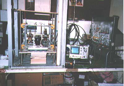
Machine (yellow wheels & black motor) in lower part of vertical test rig with control electronics to right.
This article describes a method of converting electrical power into a propulsive force that potentially generates a large propulsive thrust. In this machine thrust is produced (by rotating and reciprocating masses, solenoids on ferrous rods) in three ways:-
(a) Centrifugal Thrust
(b) Momentum Thrust
(c) Impulse Thrust
- CENTRIFUGAL THRUST
An outward force F (see Figure 1) is produced when a mass M is rotated at an angular velocity w at a radius RF = Mw2R
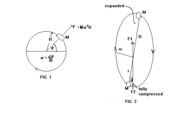
Figure 2 shows the trajectories (distorted) of two opposing masses M (solenoids), these solenoids are in a vertical plane and rotate at a speed w (radians/sec) and reciprocate in and out on ferrous rods; the opposing solenoids are joined by "tie" rods such that as one moves inwards the other moves outwards. At an angle theta (Figure 2) a current pulse is applied to the solenoids. By an electromagnetic reaction, the top solenoid is forced inwards and the bottom solenoid forced outwards. As they are also rotating, if the parameters are correctly adjusted, 1/2 a revolution later they will have exchanged positions. This action will continue:-
For the uppermost solenoidF1 = Mw2R
For the lower solenoidF2 = Mw2r
giving a net upward forceF = F1 - F2 = Mw2(R - r)
Other angular positions give a vertically resolved force (the horizontal component is arranged to cancel out).
- MOMENTUM THRUST Figures 3 & 4
As shown, in Figure 4, the inward moving solenoid is brought to a rest and gives up its momentum energy into compressing the spring, which is rotating on the FERROUS JUMP rods. This exerts a force on the hub, the solenoids are arranged to be vertical at that time, thus a maximum vertical force is generated on the hub
.
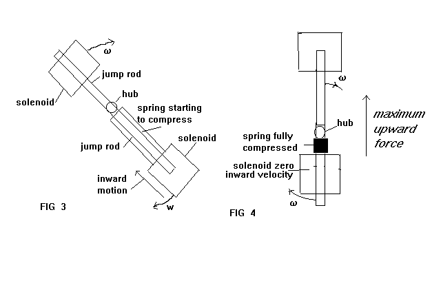
- IMPULSE THRUST
When the solenoids are pulsed when nearly vertical as in Figure 2 there will be a REACTION FORCE upwards on the upper ferrous rod F1 and upwards on the lower ferrous rod F2. These upward reaction impulse forces will be transferred to the machine through the bearing and hub, Figure 4 shows the solenoids vertical, with the lower spring fully compressed (for clarity only one spring is shown) exerting maximum upward thrust on the hub, here tending to lift the machine. The solenoid velocity is instantaneously zero, it will shortly afterwards start to move downwards under the decompressing action of the spring. After a small rotation theta (Figure 2) the solenoids are pulsed. This reciprocating and rotating action will continue.
Referring to Figure 4 the spring will be fully compressed when vertical if the following parameters are correct:-
(a) Spring Stiffness
(b) Rotation Speed
(c) Radial Speed
This will give maximum upward thrust to the hub and hence bearings and machine. A servo system has been designed to control the parameters above. This is part electronics and part computer. Parametric pumping of the solenoid current pulses will be used to optimise the power consumption by controlling the pulse width. Simple calculations show that at lower speeds the momentum thrust is larger, at higher speeds the centrifugal force is larger. In a sense the energy of the pulsing is used twice in the machine (due to rotation of the solenoids); initially when the solenoids are first pulsed the REACTION forces on the jump rods is upwards. Then half a revolution later, the "momentum thrust" is at a maximum, and again upwards.
BALANCING OUT MACHINE HORIZONTAL THRUST AND TORQUE
On the prototype machine there are two pairs of contra-rotating solenoids s1, s2, s3 and s4. These are to balance out the horizontal components of thrust. This results in a twisting torque (see Figure 5);
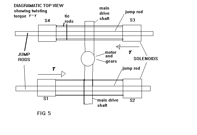
which in turn can be balanced out by two more pairs of contra-rotating solenoids s5, s6, s7, & s8, as shown diagramatically in Figure 6.
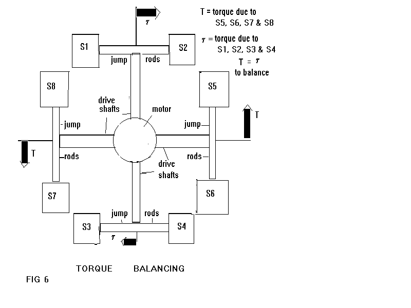
When correctly balanced this configuration results in a force in one direction (upward here). However this direction of thrust can be simply changed by varying the timing of the solenoid current pulses.
PROTOTYPE MACHINE PERFORMANCE
The machine has been run mainly at about 5 revs/sec; above about 8 revs/sec the lifting effect stops due to incorrect action.
The machine exhibits instability when run at over about 11 revs/sec, due to the inherent unbalanced nature of the solenoids i.e. a stronger framework is required.
- IN A VERTICAL THRUST MODE
A force of about 10 Newtons was obtained, with a suitable counterweight the machine has risen under the action of this force on many occasions. - HORIZONTAL THRUST MODE
The machine was mounted on a trolley (total force to move = 13 Newtons). When trolley movement was initiated (i.e. stiction force overcome) then the motion was continuous.
CONCLUSION
The machine has been observed to give a force of about 10 Newtons in horizontal and vertical modes or directions. Agreeing with simple theory calculated from F = Mw2R.
CHANGE OF THRUST DIRECTION
The direction of generated thrust can be changed from horizontal to vertical very quickly (actually in 1 machine revolution i.e. at 5 revs/sec in 200 msec); giving extreme manouverability when used to propel a moving vehicle.
SOLENOID TESTING
A simple jump test rig was constructed to test the efficiency of different types of solenoid. This basically measured the velocity of the solenoid in response to an applied current pulse (current pulses of about 10 msec being typical).Many types of solenoid were tested; a maximum velocity of about 25 m/sec was obtained for a very light coil. In practice about 4 m/sec was the maximum obtained from a heavier (0.16Kg) machine solenoid.
With a more efficient electromagnetic structure, higher velocities can be obtained (Rail Gun = 400 m/sec). The present solenoids are only about 1% efficient in converting the applied current pulses into mechanical movement of the solenoids.
Research is now going on to improve this efficiency using more complex electromagnetic structures.
ELECTRICAL POWER REQUIREMENT
If used to provide thrust for a spaceship, electrical power close to the Sun can be provided by solar panels, but beyond the orbit of Mars another source of electrical energy must be used, such as nuclear power.
CONSIDERATION OF PHYSICAL LAWS
Misconceptions of Newton's Laws are often put forward to the effect that this machine will not operate as discussed here.
Considering Newton's 1st Law:-
"A body will remain in a state of rest or uniform motion unless acted upon by an external force".
Rockets and jet engines use the principle of momentum exchange in which there is no external force, but an energy interchange. Similarly this machine has an energy (electrical) interchange to generate a force.
Regarding Newton's 3rd Law:-
"To every action there is an equal and opposite reaction".
Considering CENTRIPETAL & CENTRIFUGAL forces for a mass rotating on a rod: the centripetal force is directed towards the centre of rotation and acts on the rotating mass, accelerating it inwards and causing it to move in a circle. The reaction to this force acts at the centre of rotation, in an outward direction, and is called the centrifugal force. This is the force which generates thrust through the bearing and framework.
Einstein showed acceleration and gravity are equivalent.
In this machine considering:-
- The Centrifugal Force
The centripetal force acts inwards accelerating the mass (a solenoid) inwards. The centrifugal force acts outwards (when vertical upwards) on the hub, bearing and machine. This is an upward accelerating force. - The "Momentum Force"
The momentum upwards of the solenoid when vertical compresses the spring decelerating the solenoid, but accelerating the hub and hence machine upwards.
These two accelerations both generate forces opposing gravity.
Many (at least 12) patents U.K., P.C.T., U.S.A. have been granted to machines converting electrical rotatory energy to a "linear" mechanical force. Some of these machines are rather complex but all are based on the centrifugal idea.
Many applications are possible such as lifting and propelling helicopters and aircraft type machines, pushing boats and submarines, etc. A number of scientists and engineers have viewed this machine or a video recording of it working agreeing it works successfully.
FUTURE WORK
Detailed design and testing of the servo system is now in progress, along with rebuilding of the prototype. Considerable development needs to be done on the present prototype for a useful engine to result.
LONG TERM FUTURE WORK
Solid state engines can perhaps be developed:-
(a) Electrons rotate around in the atom with a linear speed of about 500 miles/sec. If controlled "jumping" of electrons from one level to another (orbital radius) can be achieved, large forces could be obtained.
(b)Nucleons rotate in the nucleus with relativistic speeds. If these can be used, similarly to (a) ENORMOUS FORCES WOULD RESULT.
e-mail mick@mtjf.demon.co.uk
phone Mick UK 01309 673120
or write M T French, Lynard, Tytler Street, Forres, Moray, SCOTLAND, IV36 0EL
PRESENT STATE : STATE OF PROJECT (25 7 99)
The construction of the electronic modules is now nearly complete. Although on testing the complete system some redsign may be nescessary .
As mentioned the system outputs analog quantities, which are digitized for the computer data logger by the Picolog 11 channel A / D convertor, some analog multiplexing of signals to the computer may be nesescary. With a "trade off" between no of channels digitized and speed of data collection. Additional work still needs to be done for interfacing the analog quantities from the machine to the Picolog data convertor.
The results as obtained will be outputed on to the W.W.W until the WEB site is full.A lot of data is anticipated and an interpretation key to the data will be given.
TESTING MACHINE
A variety of springs to fit on the jump rods of different k,s ( spring constant ) are about to be ordered to allow for difference in actual test performance at the design speed of 5 rotations / sec.
The SLIDER potentiometers indicating the solenoid radial position have been tested at the design speed, on the machine and found to give no contact trouble. However unfortunately log potentiometers have had to be used and no exponential to linear interpolation circuitry has been succesful in practise. To start with these log potentiomers will be used directly in log mode , although log/linear conversion may be nescessary for the machine to operate corectly.
We don't want a "New World" - We Want a "Better World"

Non Toxic Bug Killer
It's a clean kill for insect pests using this non-toxic, organic powder that's beneficial to humans and pets
Save Power
& Extend Motor Life

Paint on Insulation
Use this amazing Paint-on-Insulation to block thermal transfer far more effectively than Bat insulation
Never Buy Laundry Soap Again
Start saving all the money you have been spending on Laundry Soap. Use our Magnetic Laundry System which is non-polluting, won't damage fabrics, and comes with a Lifetime Warranty
Grow Plants Better and Faster!
With the sounds of nature and organic nutrients, you'll get greater yields, better plant vitality and natural pest resistance.
Tesla Symposium Books
From the former International Tesla Society.